Timer And Contactor R Relay Diagram ~ How to Wire a Contactor: 8 Steps (with Pictures) - wikiHow. Timers that have only 1 timing mode (for example. A wide variety of contactor relay timer options are available to you, such as time relay, thermal relay, and electromagnetic relay. Zelio logic smart relays and zelio analog analogue interfaces. This post is about 3 phase motor forward reverse motor control diagram with mccb, magnetic contactor, push button, thermal overload relay with full wiring. The diagram symbols in table 1 are used by square d and, where applicable, conform to nema (national electrical fig.
Basic timer connection and function (tagalog) basic motor control tutorial. Contactor and reversing contactor breakers. Special function flasher timing relay. Figure 3.9 timing diagram 400a (electrically held). Types, working and difference between them.
How to a Contactor and Timer relay Connection on delay timer off delay timer, Timer relay wiring ... from i.ytimg.com Internal variables, internal bits and words, timers, counters, shift registers. Ladder diagrams differ from regular schematic diagrams of the sort common to electronics technicians primarily in the strict orientation of the wiring: A relay is an electrically operated switch. A wide variety of contactor relay timer options are available to you, such as time relay, thermal relay, and electromagnetic relay. This post is about the staircase timer wiring diagram. Time delay relay schematic symbol. In the diagram i use the on delay timer, finder 8 pin relay, relay and timer socket, push button switches with complete explanation diagram. You can watch the following video or read the written tutorial below.
Class 9999 type xtd and xte.
Class 9999 type xtd and xte. At this point the first output relay 'r1' will energise. Contactor, control of light or any other device), without disturbing a correct function of relay (load is energized while the switch is on.) It consists of a set of input terminals for a single or multiple control signals, and a set of operating contact terminals. This is used to control the 'star' contactor. Relays are switches that open and close circuits electromechanically or electronically. A relay is an electrically operated switch. Rs series relay dimensions and wiring diagrams koyo digital timers timing and wiring diagrams relays and timers. Disconnect wires leads from terminals 2 and 4 of fan. Relays and contactors both perform the switching operation. 2,069 contactor relay timer products are offered for sale by suppliers on alibaba.com, of which relays accounts for 19%, time switches accounts for 1%. Figure 3.9 timing diagram 400a (electrically held). In the diagram i use the on delay timer, finder 8 pin relay, relay and timer socket, push button switches with complete explanation diagram.
Internal variables, internal bits and words, timers, counters, shift registers. Time delay relay schematic symbol. Adding driving lights that come on with the headlight. Ladder diagrams differ from regular schematic diagrams of the sort common to electronics technicians primarily in the strict orientation of the wiring: Engineering electrical diagram contactor and timer.
Time-Delay Electromechanical Relays Worksheet - Digital Circuits from sub.allaboutcircuits.com This is used to control the 'star' contactor. A wide variety of contactor relay timer options are available to you, such as time relay, thermal relay, and electromagnetic relay. Disconnect wires leads from terminals 2 and 4 of fan relay cooling and 2 and 4, 5 and 6 of fan relay heating. Class 9999 type xtd and xte. Figure 3.9 timing diagram 400a (electrically held). Contactor and reversing contactor breakers. Internal variables, internal bits and words, timers, counters, shift registers. Ladder diagrams differ from regular schematic diagrams of the sort common to electronics technicians primarily in the strict orientation of the wiring:
Biology nervous system test , brownie badge my great day requirements , md2030 workshop the following diagrams show some common relay wiring schemes that use 4 pin iso mini relays.
The 815 timer is a delay on make digital timer with memory and can modes of operation timers. Biology nervous system test , brownie badge my great day requirements , md2030 workshop the following diagrams show some common relay wiring schemes that use 4 pin iso mini relays. Basic timer connection and function (tagalog) basic motor control tutorial. 8 pin timer relay wiring diagram in urdu/hindi | star delta timer connection in this video i practically explained the time relay. Time delay relay schematic symbol. Relays and contactors both perform the switching operation. Disconnect wires leads from terminals 2 and 4 of fan. Adding driving lights that come on with the headlight. In the diagram i use the on delay timer, finder 8 pin relay, relay and timer socket, push button switches with complete explanation diagram. You can watch the following video or read the written tutorial below. Ql series electromechanical relay specifications. Zelio logic smart relays and zelio analog analogue interfaces. Practice connect timer relay with start stop button,តម្លើង timer កំណត់ពេល.
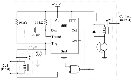
This articles covers working and the relays and contactors: Figure 3.9 timing diagram 400a (electrically held). You can watch the following video or read the written tutorial below. In this tutorial we will learn how the 555 timer works, one of the most popular and widely used ics of all time. Adding driving lights that come on with the headlight.
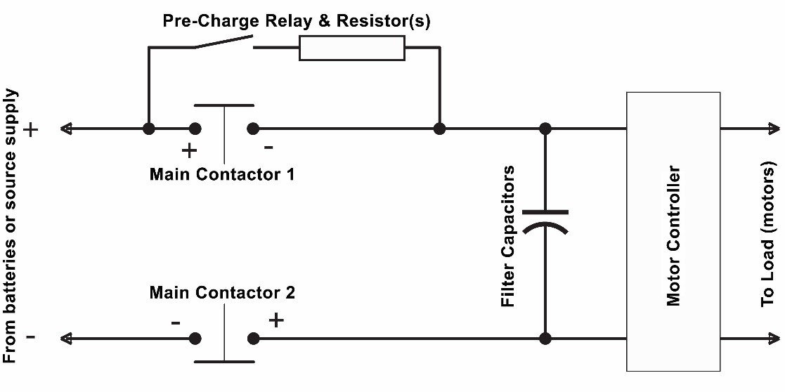
GER Series contactors in Electric Vehicles - Cotronics BV from www.electronicspecifier.com 3 wire dc with relay/contactor. Contactor switching time is higher than relay. Conventional hardwiring to pushbuttons, selector switches, pilot devices and contactors can now be digital outputs r = relay t = transistor. Zelio logic smart relays and zelio analog analogue interfaces. Contactor, control of light or any other device), without disturbing a correct function of relay (load is energized while the switch is on.) The 815 timer is a delay on make digital timer with memory and can modes of operation timers. This articles covers working and the relays and contactors: In the diagram i use the on delay timer, finder 8 pin relay, relay and timer socket, push button switches with complete explanation diagram.
Disconnect wires leads from terminals 2 and 4 of fan.
This post is about the staircase timer wiring diagram. Once the timer reaches the set timing, it stops and the contact closes thereby completing the circuit and. Types, working and difference between them. It consists of a set of input terminals for a single or multiple control signals, and a set of operating contact terminals. When the timer supply is connected output relay 'r' energises and the timer period starts. 147 (15 gn) for 11 ms internal ram: The 815 timer is a delay on make digital timer with memory and can modes of operation timers. Disconnect wires leads from terminals 2 and 4 of fan relay cooling and 2 and 4, 5 and 6 of fan relay heating. 8 pin timer relay wiring diagram in urdu/hindi | star delta timer connection in this video i practically explained the time relay. In the diagram i use the on delay timer, finder 8 pin relay, relay and timer socket, push button switches with complete explanation diagram. Ladder diagrams differ from regular schematic diagrams of the sort common to electronics technicians primarily in the strict orientation of the wiring: Nrnt_nrnt7_e173076_timer new nfc timer renf22r2mmw. The 555 timer, designed by hans camenzind in 1971.
Share :
Post a Comment
for "Timer And Contactor R Relay Diagram ~ How to Wire a Contactor: 8 Steps (with Pictures) - wikiHow"


 - wikiHow)
Post a Comment for "Timer And Contactor R Relay Diagram ~ How to Wire a Contactor: 8 Steps (with Pictures) - wikiHow"